
|
Interaction modeling allows you to lay out the detailed behavior of your objects and find appropriate homes for attributes and operations. In this fifth installment from a forthcoming book, you'll learn to update and expand your static model.
by Doug Rosenberg and Kendall Scott
Read part 1: Driving Design with Use Cases
Read part 2: Driving Design: The Problem Domain
Read part 3: Top Ten Use Case Mistakes
Read part 4: Successful Robustness Analysis
Welcome to the fifth in a series of articles that dissects the design of an Internet bookstore by following the process detailed in our first book, Use Case Driven Object Modeling with UML (Addison-Wesley, 1999). This article outlines some more common mistakes, and then explains how to correct them. Our focus will be on performing interaction modeling using UML sequence diagrams.
When you finish with domain modeling and robustness analysis, you will have uncovered most of the objects in your problem space and assigned some attributes to them. You'll have also defined static relationships among the objects on your high-level class diagram and a few dynamic relationships on your robustness diagrams. These represent fairly broad brush strokes.
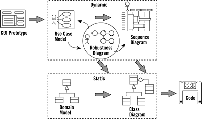
Figure 1. The "Big Picture" for Use Case Driven Object Modeling The diagram portrays the essence of a streamlined approach to software development that includes a minimal set of UML diagrams and some valuable techniques that take you from use cases to code quickly and efficiently. |
Now it's time to design how your software will really work (in other words, to define the solution to your problem). Interaction modeling is the phase where you build the threads that weave your objects together. Here, you'll start to see how your new system will perform useful behavior. Figure 1 shows where sequence diagrams reside within the big picture of the ICONIX process.
The Key Elements of Sequence Diagrams
You want to achieve three primary goals during interaction modeling.
First, allocate behavior among boundary, entity and control objects. During robustness analysis, you can identify (or at least take an educated guess at) a set of objects that can accomplish the desired behavior of your use cases. You can also break that behavior down into discrete units and create placeholder control objects for each of those units. Then you can decide which objects are responsible for which bits of behavior. If you don't have a good idea of what the relevant boundary, entity and control objects are, it's too soon to be contemplating how you'll allocate behavior. In that case, you'll need to return to robustness analysis and make sure.
Second, show the detailed interactions that occur over time among the objects associated with each of your use cases. Objects interact by sending messages to each other. These messages serve as what Ivar Jacobson calls stimuli—that is, a message stimulates an object to perform some desired action. For each unit of behavior within a use case, you must identify the necessary messages and methods.
Third, finalize the distribution of operations among classes. You should aim to have about 75 or 80 percent of your attributes defined within the static model when you finish robustness analysis. However, don't start defining operations during domain modeling and robustness analysis. In fact, we recommend that you don't assign any methods at that point, because there isn't enough information available.
Once you get to interaction modeling, however, you should have enough information. Then you can lay out the detailed behavior of your objects—on sequence diagrams, in the context of your use cases—and you can finalize finding appropriate homes for attributes and operations. While you do this dynamic modeling, you'll be updating and expanding your static model, and this will solidify your increasing knowledge of how your new system should work.
The UML's sequence diagram evolved from a combination of Jacobson's object interaction diagram and the OMT's event trace diagram. Within the ICONIX approach, sequence diagrams represent the major work product of design. You draw one sequence diagram that encompasses the basic course and all alternative courses within each of your use cases. (You can use more than one page if you need to.) The results form the core of your dynamic model—in which the system's runtime behavior, including how it will accomplish that behavior—is defined in great detail.
There are four types of elements on a sequence diagram: the text for the use cases' course of action, objects, messages and methods (operations).
The text for the use cases' course of action appears down the left-hand side. It's a good idea to break up the text with white space so it's easy to see which sentence(s) correspond with each set of elements to the right.
Objects, which you bring over directly from your robustness diagrams, are represented with two components: the name of an object and (optionally) the class to which that object belongs. These appear in a box at the top of the page, in the form object::class. A dotted line runs from that box down the length of the page. You can show the robustness diagram icons above the object boxes.
Messages are arrows between objects. A message arrow can go directly between two dotted lines, between a line and a method rectangle, or between two method rectangles.
Methods (operations) are shown as rectangles that lie on top of the dotted lines that belong to the objects to which they're assigned. You can use the lengths of these rectangles to reflect the focus of control within the sequence. A particular method is in control up to the point where its rectangle ends.
Many people get stuck at this point in a development project. (This is especially likely if they've skipped preliminary design.) The technique we'll describe next evolved from helping students get "unstuck" during dozens of training workshops during the past several years.
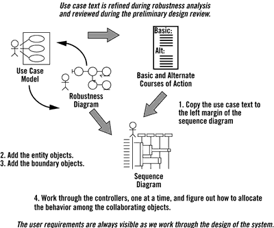
Figure 2. Four Steps for Drawing Sequence Diagrams Pasting the use case text in the sequence diagram means user requirements are always visible when working through the design. |
Figure 2 shows the four steps to perform when drawing sequence diagrams the ICONIX way. The steps are outlined as follows:
Step 1. Copy the text for the given use case from the use case specification. Paste it onto the left margin of the page. Doing so enables that text to serve as an ongoing reminder of what you need to accomplish. The result is that when you're doing the design, the required system behavior is always staring you in the face. But if you don't have all the relevant alternative courses of action written out for each of your use cases, you should not proceed until they're in place. Otherwise, the diagrams will not cover all special cases, and you won't uncover all of the use case's behavior. This means that you won't discover all of the necessary methods for your objects.
Step 2. Add the entity objects from the robustness diagram. Each of these objects is an instance of a class that appears on the class diagram that represents your static model. (If you forgot to update your static class diagrams in response to new objects discovered during robustness analysis, do it now. These objects should have most of their attributes in place. Many of them will be serving data to other objects.) You can expect to discover missing attributes as you work through your sequence diagram. Be meticulous about adding them to your static model; this is likely to be your last step before code.
Step 3. Add the boundary objects from the robustness diagram. You get a bonus point if you're wondering why we didn't mention adding boundary objects to your domain model. The reason is that these objects are part of the solution space; the domain model addresses the problem space. By accounting for boundary objects on your sequence diagrams, you begin integrating the two spaces at the start of detailed design.
If you follow the ICONIX approach, the first three steps involved in drawing sequence diagrams are completely mechanical in nature. That can be very useful in achieving momentum as you get serious about your design. The fourth step, deciding which methods go on which classes, is the essence of interaction modeling.
Step 4. Put methods on classes. This involves converting the controllers from your robustness diagram, one at a time, to sets of methods and messages that embody the desired behavior. (Occasionally, you may turn a controller into a real control object.) Use your robustness diagram as a checklist to make sure you have all the required system behavior accounted for on your sequence diagrams. Then simply check off each control object as you draw the corresponding messages on the sequence diagrams. This will help you eliminate the insidious "oops, I forgot about that function" error. (One controller on a robustness diagram can translate to several methods on a sequence diagram.)
There are two basic strategies for converting controllers that appear on robustness diagrams: control in the screen and use case controller. If you used only one strategy during your sequence diagramming efforts, that would qualify as patternizing. The idea is that the team members responsible for the diagrams should establish, early in the task, design standards that can be used across all your use cases.
On the other hand, as you're diagramming the interactions among various objects, you may decide that one or more well-established design patterns would fit in nicely. Or perhaps you might develop new patterns to establish a standardized approach to design problems that appear across multiple use cases. This is where much of the real object-oriented development takes place.
At this point, you've already checked the robustness diagrams against your use case text. By checking your sequence diagrams against your robustness diagrams, you add a measure of assurance that you're designing in response to what the user needs (in other words, meeting your requirements).
The Top 10 Sequence Diagramming Errors
The flip side of these
principles takes the form of several common errors that we've seen students
make when they're drawing sequence diagrams on their projects for the first
time. Our "top 10" list of errors follows.
10. Not doing a sequence diagram for each use case. Jacobson provided a straightforward description of the need for interaction modeling in The Object Advantage: Business Process Reengineering With Object Technology (Addison-Wesley, 1995): "It is only after you have drawn interaction diagrams [called "sequence diagrams" in the UML] for all courses of events in all use cases that you can be certain that you have found all of the roles that the system requires each object to play and, thus, the responsibilities of each object."
9. Not putting the use case text on the sequence diagram. Writing the original requirements-level text for the use case in the margin of the sequence diagram provides visual requirements traceability from the design back to your user-certified requirements. The project team will have put a lot of effort into writing the use case text, and the user community should have signed off on the results. The diagram should match the narrative flow of the associated use case.
8. Not identifying all of the necessary objects first on a robustness diagram.
If you're having trouble getting a sequence diagram started, you probably
wrote the use case incorrectly, or you didn't complete robustness analysis.
Having proper robustness diagrams that are associated with rigorously defined
use cases makes the job significantly easier. ![]()
7. Not providing a visual trace between the use case text and the message arrows. Each sentence, including appropriate fragments, within the use case text should have some white space around it. Each should also line up visually with the message or set of messages that correspond with the specified behavior. This will enable people reading the diagram to easily see how the system will accomplish what the use case describes.
6. Not showing the plumbing; instead, keep your sequence diagram at a high level of abstraction. It isn't necessary to show plumbing on robustness diagrams, since they reflect a preliminary design view. However, sequence diagrams are the last stop before coding, and as such need to show the real design in full detail.
5. Turning your sequence diagram into a flowchart instead of using it to allocate behavior among objects. Remember that the sequence diagram is the primary vehicle for making behavior allocation decisions. You're really using them to assign operations to your classes as you go. Behavior allocation—deciding which operations belong to which classes—is critical in the ICONIX approach. Decisions made during this phase of a project dictate whether the overall design is good or bad. This is where experienced designers earn their pay.
4. Not focusing on interesting methods (real software behavior), getting distracted by getters and setters.
By exploring the system's dynamic behavior, you learn which attributes and
operations are needed in your static model's classes. To start, add attributes
and methods to your classes as soon as you decide where they go in the context
of your sequence diagrams. But don't spend lots of time adding get and set
methods to your model. You should take advantage of the principle of encapsulation:
Only allow access to attributes via getters and setters. ![]()
3. Not thinking carefully about the origins of the message arrows (in other words, which object is in control at any given time). Messages between objects invoke the operations on the associated classes. Although it's not important to get the arrows right on robustness diagrams, it's essential to get them right on sequence diagrams. The flow of control needs to be explicit. It should be obvious at all times which object is in control.
2. Not following basic principles of responsibility-driven, object-oriented development when allocating behavior by drawing message arrows. An object (and, by extension, a class) should have a single personality. This means a class should be focused on a strongly related set of behaviors. This parallels the well-established rules that state objects should be highly cohesive and loosely coupled. Other principles you should focus on include reusability (the more general your objects and classes, the more likely they are to be reusable for other projects and applicability. When you assign methods to the objects on your sequence diagrams, always ask whether there seems to be a good fit between method and object, and also whether the task the method performs is obviously relevant to the object.
1. Not updating your static model as you go by building local class diagrams for each package of use cases. It's nice to keep a clean set of domain classes on a pure domain model diagram. However, it's also a good idea to draw localized static class diagrams that show both solution space objects and problem space objects. A good guideline for this is one such diagram per package of use cases. As you come up with scaffolding and other types of infrastructure, such as helper classes, put them on the static class diagram, as well. This is where you shift your focus from the problem space to the solution space. It's best to use localized class diagrams—say, one per use case package—because by this time your static model is probably too expansive to be captured within one readable diagram. Doing this also lets you split work across teams.
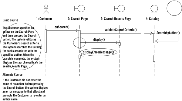
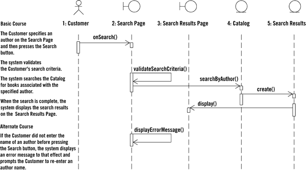
A sequence diagram that contains violations of four of the top 10 rules (outlined in the following bullet points) is shown in Figure 3. The mistakes are corrected in Figure 4.
Figure 3. Sequence Diagrams with Violations This sequence diagram violates four of the top 10 rules. Can you spot them? |
Figure 4. Corrected Sequence Diagram Violations to rule seven, eight, three and two have been corrected. |
Stay tuned for an additonal three articles, which provide a prepublication look at the annotated example from our forthcoming book, Applied Use Case Driven Object Modeling (Addison-Wesley, 2001; now tentatively scheduled for June).We hope the previous five articles in our modeling tutorial have provided you with an effective process for designing e-commerce systems by illustrating how to build a domain model with loosely coupled classes, write concise use cases, do effective robustness analysis and create successful sequence diagrams.
Note: ![]() symbolizes analysis paralysis
symbolizes analysis paralysis